History of TFT LCD
·In 1957, John Wallmark of RCA obtained a patent for the thin-film MOSFET.
·In 1992, Paul K. Weimer of RCA developed thin film transistor (TFT) technology using Wallmark patents.
·In 1968, Bernard Lechner of RCA implemented TFT technology in a liquid crystal screen (LCD) for the first time.
·In 1971, Lechner, FJ Marlowe, EO Nester, and J.Tults demonstrated a 2x18 matrix display driven by a hybrid circuit using a dynamic diffusion model of an LCD screen.
·In 1974, Brody and Fang Chen Luo proposed the first planar active matrix liquid crystal (LCD AM) screen using CdSe TFT.
·In 1975, Brody invented the term "active matrix LCD".
·2020-LCD TFT display technology currently dominates the display market. It has destroyed the market for CRTs (cathode ray tubes) and plasmas over the past 20 years. The only challenge is OLED (organic light-emitting diode) and micro-LED.
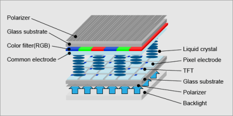
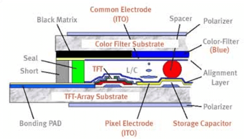
TFT (Thin Film Transistor Liquid Crystal Display) LCD scren technology has a sandwich structure in which glass panels are filled with liquid crystals. A polarizing filter, color filter (RGB, red/green/blue) and two adjustment layers determine exactly how much light can pass through and what color is created. Each pixel in the active matrix is connected to a transistor containing a capacitor so that each subpixel can retain its charge rather than having to send it out every time it needs to be replaced. The TFT layer controls light flow, color filters display color, and the top layer contains the visible screen.
The TFT LCD structure is shown in Figure 1

The charge is used to cause the liquid crystal material to change its molecular structure, allowing various backlight wavelengths to "pass through." The active matrix of the TFT screen is constantly flowing and quickly changes or refreshes based on input signals from the control device. The pixels of a TFT screen are determined by the color matrix and underlying density (resolution) of the TFT layout. The more pixels you have, the more detail you can get. Available screen sizes, power consumption, resolution, interfaces (how to connect) define TFT screens. The pixels of a TFT screen are determined by the color matrix and underlying density (resolution) of the TFT layout. The more pixels you have, the more detail you can get. TFT screens by themselves cannot emit light like OLED screens and must be combined with a bright white backlight to produce an image. Newer panels use LED backlighting to generate light, thus using less energy and less design depth. TFT display module includes TFT screen, LED backlight and control circuit.
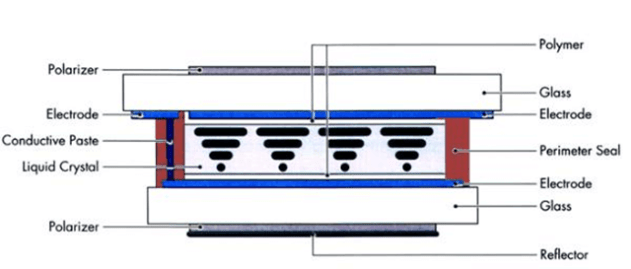
LCD TFT has several advantages over other types of screens (CRT, plasma). It is thin, light, energy-saving, and supports portable devices such as mobile phones, laptops, wall-mounted LCD TVs, and flat-panel monitors. LCD TFTs are also relatively cheap, allowing them to control the display space. When we say types of LCD screens, we are referring to two types of LCD screens: active TFT color screens and passive monochrome screens. Before the invention of TFT screens, the world had been using passive matrix LCD screens for many years. Passive matrix LCDs can only be used with monochrome screens such as calculators, clocks (without iWatch), thermostats (without Nest), meters, etc. With LCD TFT, the world becomes more colorful.

Figure 2 Active TFT color display

Figure 3 Monochrome passive LCD display
New TFT technology
TFT LCD technology has always had problems with viewing angles and slow response times. Thanks to the new TFT LCD and IPS display technology, we have not encountered such problems in the market. In future developments, TFT LCD screens will become larger (Samsung launched 146 inches at CES 19), high resolution (8K 7680×4320 pixels), high speed suitable for games, wide enough viewing angles up to 170 degrees and High enough contrast. Meeting the requirements of the most demanding aerospace computer monitors, the high image quality is suitable for the most critical medical and surgical displays and is combined with a capacitive touch screen (OCAP).