Many color displays use resistive displays. Resistive displays include four-wire, five-wire, and six-wire multi-wire resistive displays. This article focuses on the structure of the most common four-wire capacitive display.
General structure of resistive display screen
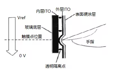
The resistive touch screen is a resistive film screen that is tightly attached to the surface of the display. It is composed of multiple layers of composite films. A piece of glass or organic glass is used as the lower substrate, and its upper surface is coated with an ITO transparent conductive layer. The lower substrate is covered with a plastic sheet or glass sheet, and its lower surface is also coated with an ITO transparent conductive layer, while its upper surface (i.e., outer surface) is hardened and smooth and scratch-resistant. There are many small transparent insulating isolation points between the two conductive layers to isolate them. When a finger touches the screen, the two conductive layers come into contact at the touch point. The two-layer ITO film working surface of the resistive touch screen must be complete. Apply a strip of silver conductive glue on both sides of each working surface, apply a voltage of 5V to one end and a voltage of 0V to one end, so that a uniform and continuous layer can be formed on the working surface. voltage distribution.
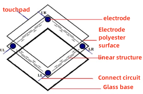
Structure of four-wire capacitive display
The four-wire resistive touch screen is an early resistive touch screen. It consists of an upper diaphragm (0.2mm thick glass or plastic film) and a lower substrate (0.7~1.1mm thick glass). The inner surface between the upper and lower sheets is coated with ITO film. The ITO film is used as a uniform resistance layer, and the sheet resistance is about 200~300/port. The lower substrate uses a photolithography process to form dense and evenly arranged small bumps on the ITO film layer. The purpose is to separate the ITO film layer into several small intervals to improve the resolution of the touch screen.
Use screen printing to print two silver electrodes on both lateral sides of the lower substrate ITO film layer and on the vertical sides of the upper diaphragm ITO film layer. The sheet resistance should be more than 3000 times smaller than that of ITO. There is usually a gap of 0.1~0.3mm between the upper and lower pieces. A spherical gasket is installed between the gaps. The height of the gasket is 5~10um. The distribution diameter of the spherical gasket should be less than 50um. The four electrodes are led out through flexible cables, and the upper and lower pieces are pressed together with sealant or double-sided tape to form a complete touch screen. By attaching the touch screen to the LCD surface and connecting the corresponding control circuit and the interface circuit between the touch screen and LCD, it can be used in various products.
The following picture shows the Hot Display four-wire resistive touch screen: Figures 1 to 2 show the touch screen and the effect after assembly on the display screen respectively.
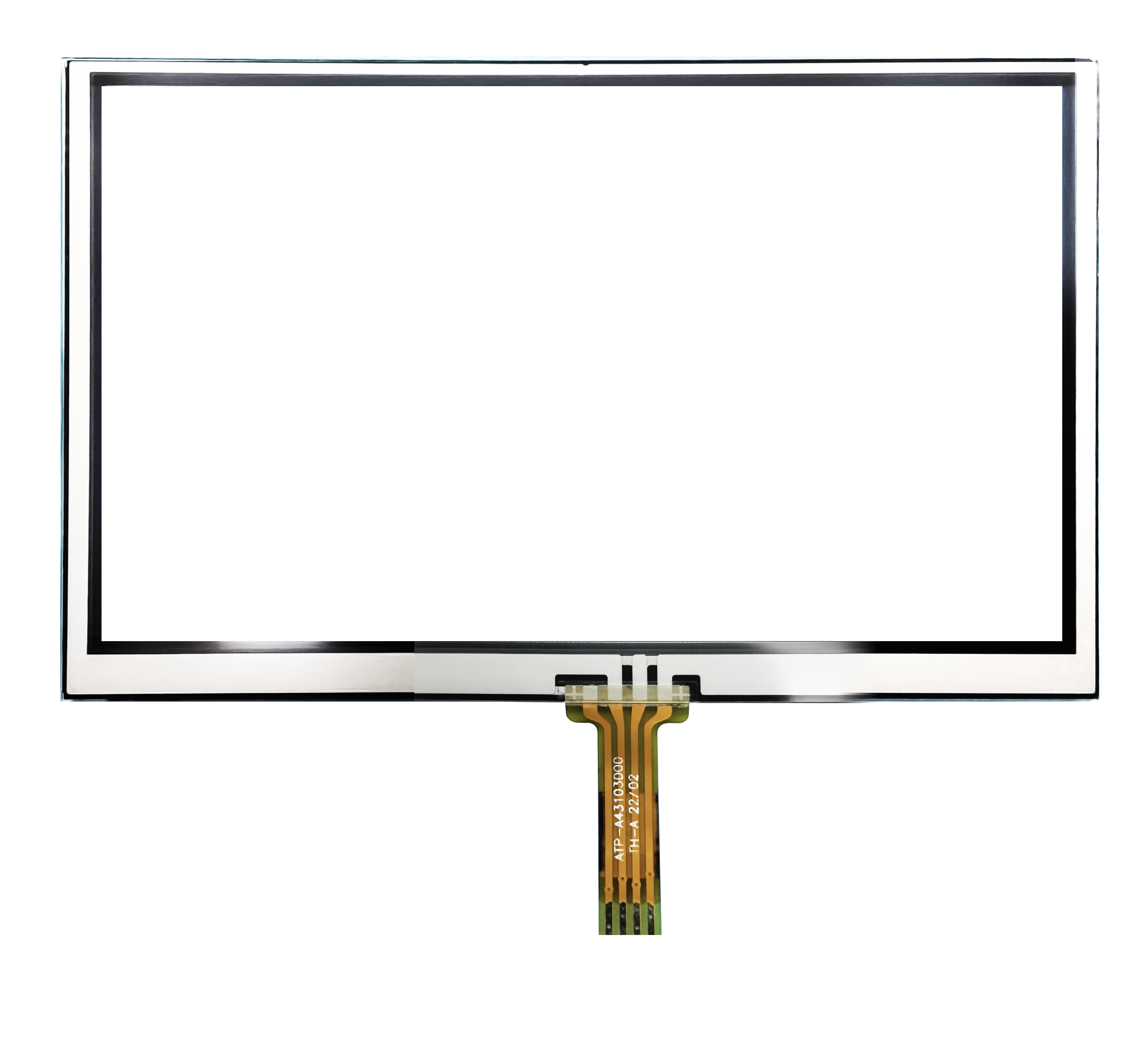
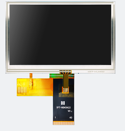
(Figures 1) (Figures 2)
Examples of Hot Display four-wire resistive touch screen products
Model: 3.5-inch TFT vertical screen/320*480 resolution/full
viewing angle/TFT-H035A3HVIST4R50
Type: TFT vertical screen
Display pixels: 320x480
Overall dimensions (mm): 54.76x83.58x2.5
VA size (mm): 3.5
AA size (mm): 3.5
Effective size mm: 48.96x73.44
Application: Outdoor instrumentation
Viewing angle: full view
Backlight/brightness: 400cd/m2
Pin: FPC-50PIN
Interface mode: MCU
Special instructions: Antistatic ESD 8KV
Working temperature: -20~70℃
Supply voltage: 3.3v
Driver chip: ST7796S
Four-wire resistive touch screen Hot Display product structure diagram and key product parameters
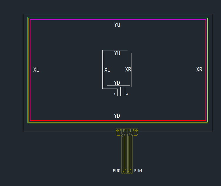
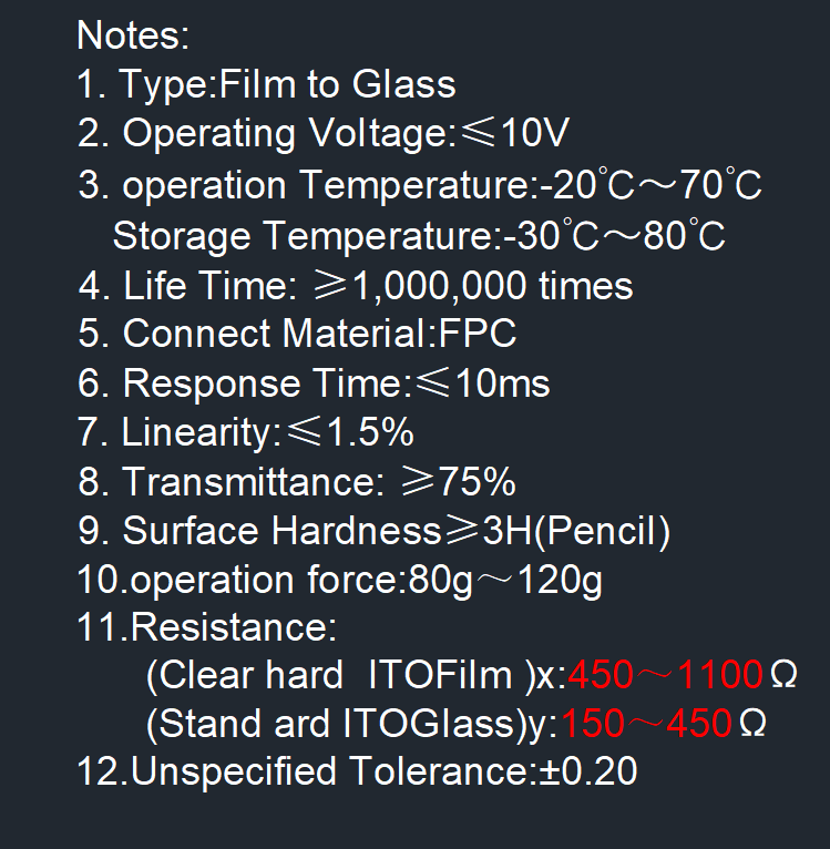
(Hot Display Product Structure Chart) (key parameter)