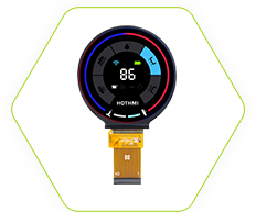
 4.2-Inch TFT LCD Display Module1280x960 MIPI DSI Interface High Brightness Screen With GH7005 Now Available!
 English
 简体中文
简体中文
 日本語
日本語 Deutsch
 한국어
한국어 Русский язык
 Español
 Français


20+years of manufacturing experience:Founded in 2004, HOTDISPLAY Technology Co., Ltd. is a leading LCD manufacturer dedicated to providing cutting-edge solutions to different industries. We specialize in the design and production of high-performance LCD modules, including monochrome TFT Display Panels, COG LCD Modules, Graphic LCD Modules, Character LCD Modules、Touch Panels、OLED Segment LCD Displays. With our relentless focus on innovation, quality, and customer-centric service, we deliver advanced visualization technologies to our partners around the world.
We have an experienced R&D team. Quality,we are solid,Innovation,we never give up!We are committed to providing you with the best display solutions!
You only need to put forward an idea, and our R&D engineers can design a unique display application for you.

Since its establishment in 2004, HOTDISPLAY Technology Co., Ltd. has focused on the research and development, design and manufacturing of liquid crystal displays, and its products cover monochrome LCD, TFT LCD, graphic LCD and other types. The company has independent intellectual property rights, has obtained a number of patents and software copyrights, and is committed to innovation and quality assurance. Its products are widely used in multiple industries such as AI, 5G, smart home, and have about 200 customers in more than 50 countries and regions around the world. The company has always adhered to the concept of "taking root in China and serving the world". It has more than 1,500 domestic customers and has maintained long-term cooperative relations with most customers for more than 10 years.
HotDisplay is a leading Chinese manufacturer of displays and a global supplier with over 20 years of experience in the digital display industry. Renowned for providing high-quality products, excellent services, and customized design solutions, we have earned the trust of customers worldwide. With a portfolio of over 1000 products and collaborations with more than 2000 partners, we boast extensive design and manufacturing expertise. Our commitment to quality control and state-of-the-art automated production lines ensures our capability to deliver innovative and reliable display solutions.
As a trusted LCD display manufacturer, designer and supplier, HOTDISPLAY Technology Co., Ltd. has been serving many industries since 2004. We produce TFT color screen, serial port screen, smart screen, LCD module, COG module, HI driver-free module, IPS full viewing angle, high brightness industrial screen, OLED LCD screen, OLED module screen, segment code LCD screen, PCAP module, sensor touch screen, custom industrial screen, resistive screen, capacitive screen.
years of industry experience
engineers and 150 skilled workers
m2/yr of LcD panels
million pcs/year LCD modules
million pcs/year touch panels
million pcs/year LCD backlights
In this article, we will explore a variety of LCD display failure modes, their root causes, and practical solutions. We will also introduce two ingenious low cost diagnostic methods using a pointer type multimeter or even just a piece of wire and a desk lamp. Whether you are a hobbyist, a technician, or an engineer, this guide will help you quickly identify and resolve LCD display issues.
Learn More >>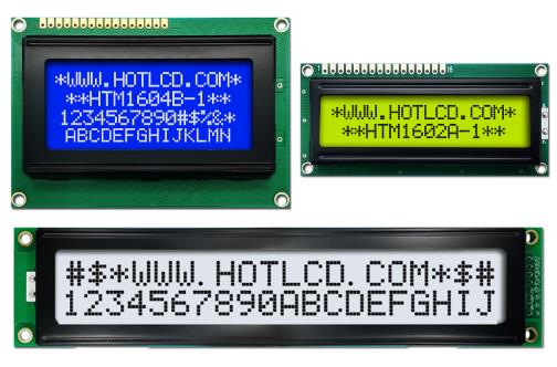
This article introduces the features, structure, advantages, and customization solutions of character LCD displays, emphasizing their low power consumption, high integration, easy programmability, and wide range of application scenarios.
Learn More >>
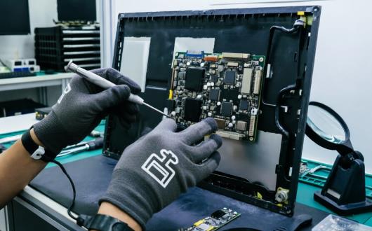
A complete LCD monitor is not merely a window for displaying images, but rather an information processing terminal that performs a multitude of functions—including signal conversion, image optimization, user interaction, and system protection. This level of integration directly translates into significant advantages for LCD monitors in terms of usability, reliability, and functional richness.
Learn More >> China LCD TFT Display Manufacturer, Global Supplier
Address:Building N3, Tian'an Digital Industry Park, Fenggang Town, Dongguan City, Guangdong Province, China


 Custom heating plates